- 您现在的位置:买卖IC网 > Sheet目录233 > LOK4001-2RLD (Power-One)DIN RAIL 26W 5.1V
�� ��
��
��LOS,� LOR,� LOK4000� Series� Data� Sheet�
�?�
�Safety� and� Installation� Instructions�
�DIN-Rail� Mountable� AC-DC� (DC-DC)� Converters�
�Installation� Instructions�
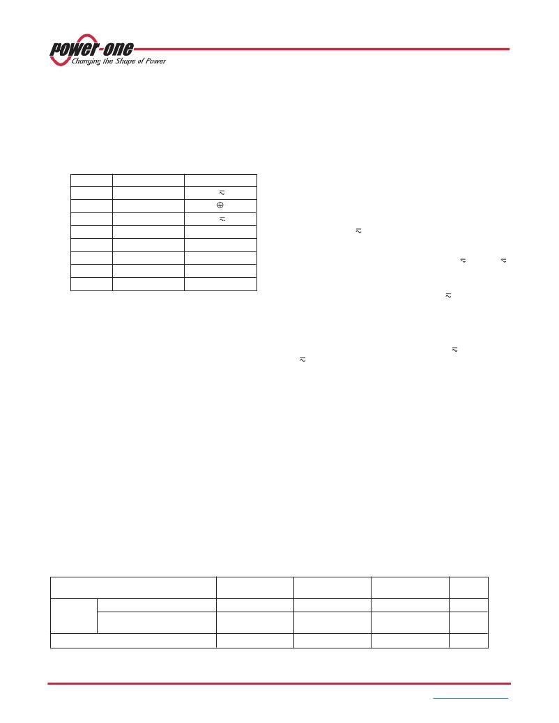
�Terminal� Allocation�
�The� terminal� allocation� table� defines� the� electrical� potentials� of�
�the� AC-DC� converters.� For� mechanical� positions� of� the�
�terminals� see� Mechanical� Data� .�
�These� converters� are� components,� intended� exclusively� for�
�inclusion� within� other� equipment� by� an� industrial� assembly�
�operation� or� by� professional� installers.� Installation� must� strictly�
�follow� the� national� safety� regulations� in� compliance� with� the�
�enclosure,� mounting,� creepage,� clearance,� casualty,� markings�
�and� segregation� requirements� of� the� end-use� application.�
�Table� 9:� Terminal� allocation�
�Terminal� Electrical�
�LOK/LOR/LOS�
�Connection� to� the� system� shall� be� according� to� Terminal�
�allocation� and� Mechanical� Data� .� Check� for� hazardous� voltages�
�before� altering� any� connection.�
�1�
�2�
�3�
�4�
�5�
�6�
�7�
�8�
�Input� (fused)�
�Protective� earth�
�Input�
�D/Output� (positive)�
�Output� (positive)�
�Output� (negative)�
�Output� (negative)�
�R� input� or� open�
�L�
�N�
�D� /+�
�+�
�–�
�–�
�R� /� n.c.�
�Ensure� that� a� converter� failure� (e.g.� by� an� internal� short-circuit)�
�does� not� result� in� a� hazardous� condition.� See� also� Safety� of�
�operator� accessible� output� circuit� .�
�The� phase� input� (� L� )� is� internally� fused� by� a� 1.6� A� slowblow�
�type.� It� is� not� customer-accessible.� This� fuse� is� designed� to�
�protect� the� unit� in� case� of� overcurrent.� Option� F� or� external�
�fuses� in� the� wiring� to� one� or� both� input� lines� (� L� and/or� N� )�
�may� therefore� be� necessary� to� ensure� compliance� with� local�
�requirements.�
�A� second� fuse� in� the� wiring� to� the� terminal� N� is� needed� if:�
�?� Local� requirements� demand� an� individual� fuse� in� each�
�Standards� and� Approvals�
�All� models� are� safety-approved� according� to� the� standards�
�IEC/EN� 60950-1� and� UL/CSA� 60950-1� 2� nd� Edition.�
�All� models� are� UL� 508-listed� to� UL� 508� .�
�These� converters� have� been� evaluated� for:�
�?� Class� I� equipment.�
�?� Building� in� with� vertical� mounting� on� a� DIN-rail.�
�?� Double� or� reinforced� insulation� or� an� earthed� part� between�
�input� and� output.�
�?� Basic� insulation� between� input� and� earth�
�?� Functional� insulation� between� output� and� earth�
�?� Pollution� degree� 2� environment�
�?� Connecting� the� input� to� a� primary� circuit� with� overvoltage�
�category� II.�
�The� converters� are� subject� to� manufacturing� surveillance� in�
�accordance� with� the� above� mentioned� standards.�
�For� details� see� the� Declaration� of� Conformity� (last� 2� pages).�
�Protection� Degree�
�IP� 20:� All� models.�
�Table� 10:� Isolation�
�source� line�
�?� Neutral� and� earth� impedance� is� high� or� undefined�
�?� Phase� and� neutral� of� the� mains� are� not� defined� or� cannot� be�
�assigned� to� the� corresponding� termials� (� L� to� phase� and�
�N� to� neutral).�
�Note:� Do� not� open� the� converters,� or� guarantee� will� be�
�invalidated.�
�Make� sure� that� there� is� sufficient� air� flow� available� for�
�convection� cooling.� This� should� be� verified� by� measuring� the�
�case� temperature� when� the� unit� is� installed� and� operated� in� the�
�end-use� application.� The� maximum� specified� case�
�temperature� T� C� max� shall� not� be� exceeded.�
�Note:� The� converters� are� designed� for� vertical� mounting� on� a�
�DIN-rail.� If� a� converter� is� operated� as� well� in� a� horizontal�
�position,� the� measuring� point� T� C� should� be� located� on� the� top.�
�Isolation�
�The� electric� strength� test� is� performed� in� the� factory� as� routine�
�test� in� accordance� with� EN� 50116� and� IEC/EN� 60950� and�
�should� not� be� repeated� in� the� field.� Power-One� will� not� honor�
�any� warranty� claims� resulting� from� electric� strength� field� tests.�
�Characteristic�
�Input� to�
�protective� earth�
�Input� to�
�output�
�Output� to�
�protective� earth�
�Unit�
�Electric�
�strength�
�test� voltage�
�Actual� factory� test� ≥� 1� s�
�AC� test� voltage� equivalent�
�to� actual� factory� test�
�2.1�
�1.5�
�2.1� 1�
�1.5� 1�
�1.4�
�1.0�
�kVDC�
�kVAC�
�Insulation� resistance� at� 500� VDC�
�>300�
�>300�
�>100�
�M� ?�
�1�
�In� accordance� with� EN� 50116� and� IEC/EN� 60950,� subassemblies� are� pre-tested� with� 4.3� kVDC� or� 3.0� kVAC.�
�BCD20035-G� Rev� AB,� 23-Jun-2011�
�Page� 9� of� 10�
�www.power-one.com�
�发布紧急采购,3分钟左右您将得到回复。
相关PDF资料
LP0125CCKW01A
SWITCH PUSHBUTTON DPDT 3A 125V
LP0125CMKW015FB
SWITCH PUSHBUTTON DPDT 3A 125V
LPI50XXX1K247XX
SWITCH PUSHBUTTON DPST 5A 12V
LRA32H2BBALN
SWITCH ROCKER DPST 10A 125V
LRA511-CR-1/012V
SWITCH ROCKER SPST 10A 30V
LRGSEK610-RS-B-A/125N
SW ROCKER DPST 20A SLD
LS1571-11-BL-BL-012
SWITCH ROCKER SPDT 15A 125V
LS431450
SCR MOD ISO SGL 1400V 500A
相关代理商/技术参数
LOK4001-2RLDG
制造商:Power-One 功能描述:DIN RAIL 26W 5.1V
LOK4001-2RLD-G
功能描述:DIN导轨式电源 50W 5.1V O-DIN-RAIL RoHS:否 制造商:Mean Well 产品:Linear Supplies 商用/医用:Commercial 输出功率额定值:960 W 输入电压:180 VAC to 264 VAC, 254 VDC to 370 VDC 输出端数量:1 输出电压(通道 1):48 V 输出电流(通道 1): 输出电压(通道 2): 输出电流(通道 2): 输出电压(通道 3): 输出电流(通道 3): 尺寸:150 mm L x 110 mm W
LOK4140-2RLD
功能描述:DC/DC转换器 DIN Rail 49W (12.84V) Battery Charger RoHS:否 制造商:Murata 产品: 输出功率: 输入电压范围:3.6 V to 5.5 V 输入电压(标称): 输出端数量:1 输出电压(通道 1):3.3 V 输出电流(通道 1):600 mA 输出电压(通道 2): 输出电流(通道 2): 安装风格:SMD/SMT 封装 / 箱体尺寸:
LOK4140-2RLDG
制造商:Power-One 功能描述:DIN RAIL FLOAT CHARGER 50W 12V
LOK4140-2RLD-G
功能描述:DIN导轨式电源 50W 12-15V Btry Chgr O-DIN-RAIL MOUNT RoHS:否 制造商:Mean Well 产品:Linear Supplies 商用/医用:Commercial 输出功率额定值:960 W 输入电压:180 VAC to 264 VAC, 254 VDC to 370 VDC 输出端数量:1 输出电压(通道 1):48 V 输出电流(通道 1): 输出电压(通道 2): 输出电流(通道 2): 输出电压(通道 3): 输出电流(通道 3): 尺寸:150 mm L x 110 mm W
LOK4240-2RLD
功能描述:DC/DC转换器 DIN Rail 49W (25.7V) Battery Charger RoHS:否 制造商:Murata 产品: 输出功率: 输入电压范围:3.6 V to 5.5 V 输入电压(标称): 输出端数量:1 输出电压(通道 1):3.3 V 输出电流(通道 1):600 mA 输出电压(通道 2): 输出电流(通道 2): 安装风格:SMD/SMT 封装 / 箱体尺寸:
LOK4240-2RLDG
制造商:Power-One 功能描述:DIN RAIL FLOAT CHARGER 50W 24V
LOK4240-2RLD-G
功能描述:DIN导轨式电源 50W O-O-DIN-RAIL Mountable AC-DC RoHS:否 制造商:Mean Well 产品:Linear Supplies 商用/医用:Commercial 输出功率额定值:960 W 输入电压:180 VAC to 264 VAC, 254 VDC to 370 VDC 输出端数量:1 输出电压(通道 1):48 V 输出电流(通道 1): 输出电压(通道 2): 输出电流(通道 2): 输出电压(通道 3): 输出电流(通道 3): 尺寸:150 mm L x 110 mm W